In many applications, it is easy to see that a structure moves. What is much harder is understanding what that movement means mechanically.
Some systems cannot be measured directly in their real operating environment. In other cases, researchers and developers may not have access to the equipment, expertise, or time needed to build a complete force measurement setup themselves.
Our approach combines microrobotics, small-scale force measurement, and digital image correlation (DIC). First, the structure is mechanically characterized under controlled conditions. It can then be used later as a calibrated mechanical readout in the final application, where direct force measurement may not be practical.
The key idea is to separate mechanical characterization from the final use case.
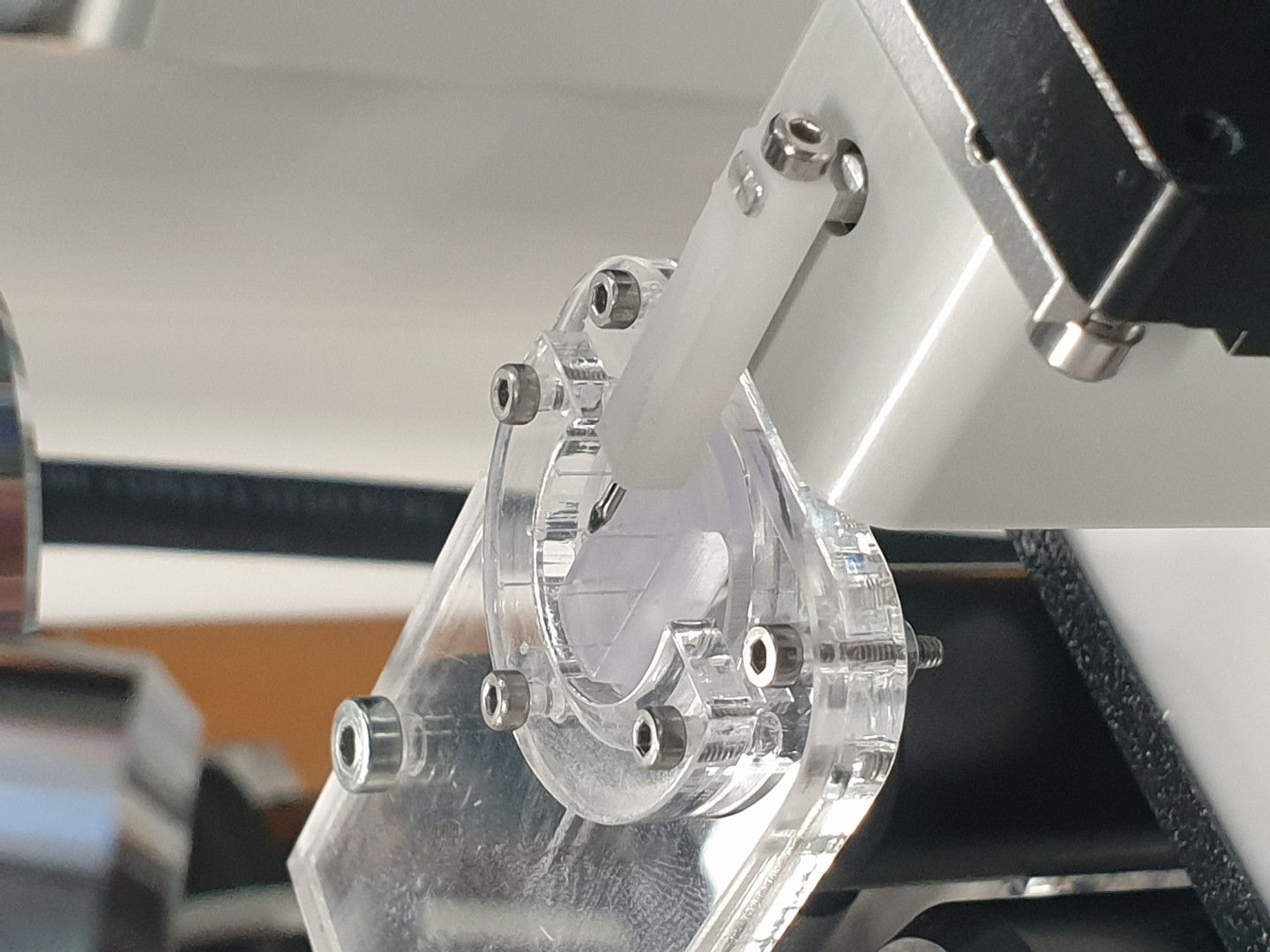
In the first stage, the structure is deformed in a controlled and repeatable way using microrobotics. At the same time, force is measured with a sensitive small-scale setup while DIC tracks the deformation optically.
This creates a calibration between visible deformation and mechanical response. Once that relationship is known, the structure can later be used in the real application as a calibrated response element.
Many systems are difficult to measure directly in their actual environment. The limitation may come from liquids, contamination risk, fragile samples, limited space, or conditions that are simply incompatible with conventional force sensors.
Sometimes the challenge is also practical. End users may be specialists in biology, materials, chemistry, or product development, but not in force sensing, calibration, or precision mechanics. They still need reliable mechanical insight, but not necessarily a complete in-house measurement platform.
That is where this workflow becomes valuable. Instead of forcing the final application to include direct force measurement, the structure itself can first be characterized and later used as a calibrated mechanical readout.
One example is a system where cells grow between two flexible micro-pillars.
As the cells contract, they bend the pillars. Direct force measurement in that biological environment is not always practical, especially when the setup involves liquid media and contamination-sensitive conditions. However, the pillars can be mechanically characterized beforehand.
Once the deformation-force relationship of the pillars is known, DIC can be used during the biological experiment to track pillar bending. From that observed deformation, the force generated by the cells can be estimated.
Cells are only one example. The broader capability is much wider: whenever a structure can be characterized first and observed later, its deformation can be used as a calibrated mechanical readout.
DIC is often used to track motion, displacement, or strain. When combined with prior mechanical characterization, it becomes more than a visualization tool.
It becomes a way to convert observed deformation into mechanical information. That opens possibilities in applications where direct force measurement would otherwise be too difficult, too invasive, or simply unavailable.
For Fibrobotics, this is part of a broader capability: developing application-specific measurement concepts for small, sensitive, and difficult-to-access systems.
Not every application needs the same measurement architecture. In some cases, the best solution is not to force a complete sensor system into the final use environment, but to characterize the relevant structure first and then read its response optically in the real application.
This kind of approach can make demanding measurements more practical for researchers, developers, and companies working with systems that are small, fragile, contamination-sensitive, or otherwise difficult to measure directly.
This example focuses on one concept, but the underlying logic is much broader. Whenever deformation can be linked to mechanical response through controlled characterization, it becomes possible to turn visible structural behavior into useful mechanical insight.
If you are interested in developing a similar measurement concept for your application, please contact us.
If you were interested in the shear properties of a composite structure, you would measure them conventionally on a laminate scale. Applicable tests would be e.g., short beam shear, v-notch shear or ±45° tension shear tests. Each of these tests requires a unique sample and usually additional sensors e.g., strain gauges or digital image correlation systems. When the setup is complex, it increases the amount of time needed for testing, material usage grows, and there are added sources of errors. And when researching natural fibres, surface treatments, or experimental materials, this scale might not be possible when materials are scarce. Then it might be wise to change to microscale measurements.
Micromechanical testing has been around for decades, and there are multiple methods to measure the interfacial shear strength (IFSS) of a fibre matrix interface. The most well-known methods are microbond, pull-out, and single fibre fragmentation tests. These methods have had problems, either in sample manufacturing or getting consistent results from the measurements. There is a rising interest at the moment in multiscale modeling, where microscale properties of the material are the starting point for understanding the laminate behavior of composite materials. Industries are also interested in new materials, e.g., natural fibres, lignin and/or cellulose-based carbon fibres, vitrimers, and thermoplastic composites. These have increased the need for rapid testing equipment, which does not require pilot-scale production of materials. The aforementioned drivers have been one of the key factors in the development of FIBRODrop and FIBROBond devices. They can create a large set of samples from a small amount of material and measure them in a hasty schedule.


FIBRODrop and FIBROBond devices together are an excellent choice for developing sizings, characterization of new materials, comparison of batches of products, or determining the material properties for models. For testing, you would only need ~30 cm of rowing or tow and 100g of thermoset resin (or a few granulates of thermoplastic polymer) to perform the microbond measurements.
So, why would you waste your time measuring on macroscale and just save your energy and start measuring in microscale today? Hit us with a call, email, fill out the form or follow us @linkedin and we will guide you toward microscale measurements.