In many applications, it is easy to see that a structure moves. What is much harder is understanding what that movement means mechanically.
Some systems cannot be measured directly in their real operating environment. In other cases, researchers and developers may not have access to the equipment, expertise, or time needed to build a complete force measurement setup themselves.
Our approach combines microrobotics, small-scale force measurement, and digital image correlation (DIC). First, the structure is mechanically characterized under controlled conditions. It can then be used later as a calibrated mechanical readout in the final application, where direct force measurement may not be practical.
The key idea is to separate mechanical characterization from the final use case.
In the first stage, the structure is deformed in a controlled and repeatable way using microrobotics. At the same time, force is measured with a sensitive small-scale setup while DIC tracks the deformation optically.
This creates a calibration between visible deformation and mechanical response. Once that relationship is known, the structure can later be used in the real application as a calibrated response element.
Many systems are difficult to measure directly in their actual environment. The limitation may come from liquids, contamination risk, fragile samples, limited space, or conditions that are simply incompatible with conventional force sensors.
Sometimes the challenge is also practical. End users may be specialists in biology, materials, chemistry, or product development, but not in force sensing, calibration, or precision mechanics. They still need reliable mechanical insight, but not necessarily a complete in-house measurement platform.
That is where this workflow becomes valuable. Instead of forcing the final application to include direct force measurement, the structure itself can first be characterized and later used as a calibrated mechanical readout.
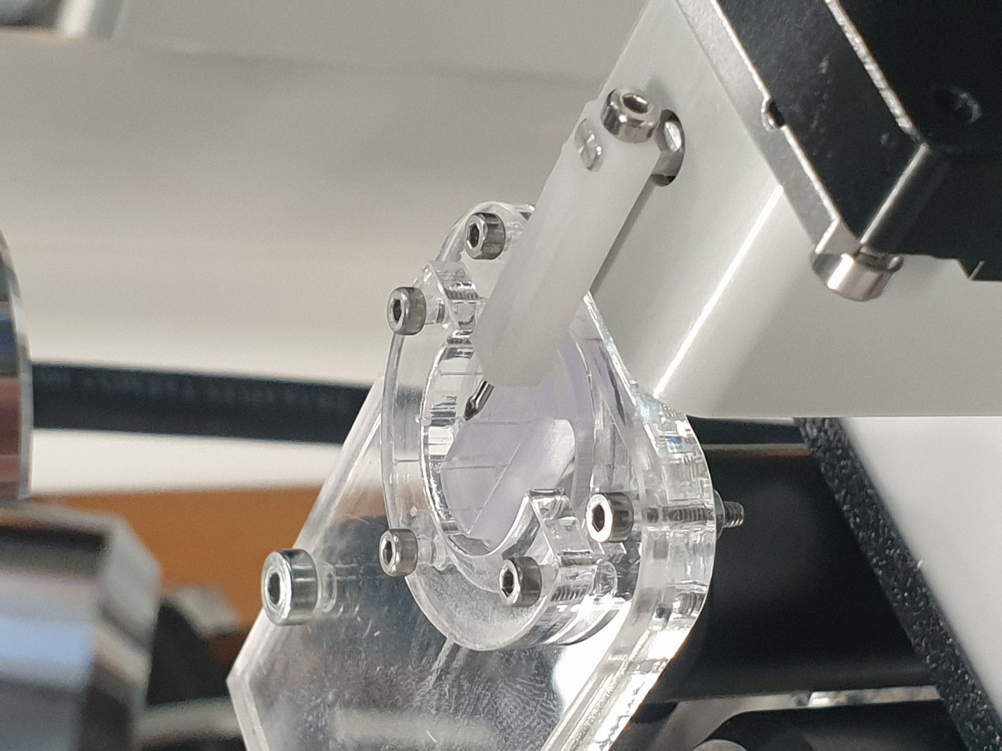
One example is a system where cells grow between two flexible micro-pillars.
As the cells contract, they bend the pillars. Direct force measurement in that biological environment is not always practical, especially when the setup involves liquid media and contamination-sensitive conditions. However, the pillars can be mechanically characterized beforehand.
Once the deformation-force relationship of the pillars is known, DIC can be used during the biological experiment to track pillar bending. From that observed deformation, the force generated by the cells can be estimated.
Cells are only one example. The broader capability is much wider: whenever a structure can be characterized first and observed later, its deformation can be used as a calibrated mechanical readout.
DIC is often used to track motion, displacement, or strain. When combined with prior mechanical characterization, it becomes more than a visualization tool.
It becomes a way to convert observed deformation into mechanical information. That opens possibilities in applications where direct force measurement would otherwise be too difficult, too invasive, or simply unavailable.
For Fibrobotics, this is part of a broader capability: developing application-specific measurement concepts for small, sensitive, and difficult-to-access systems.
Not every application needs the same measurement architecture. In some cases, the best solution is not to force a complete sensor system into the final use environment, but to characterize the relevant structure first and then read its response optically in the real application.
This kind of approach can make demanding measurements more practical for researchers, developers, and companies working with systems that are small, fragile, contamination-sensitive, or otherwise difficult to measure directly.
This example focuses on one concept, but the underlying logic is much broader. Whenever deformation can be linked to mechanical response through controlled characterization, it becomes possible to turn visible structural behavior into useful mechanical insight.
If you are interested in developing a similar measurement concept for your application, please contact us.
Every composites project pays for learning. The only question is whether you pay early and cheaply, or late and expensively. When interface performance is validated only after laminate scale-up, teams burn weeks on sample manufacturing, tie up people and equipment, and sometimes discover critical issues when schedules are already locked.
Microscale microbond testing flips that equation. With small amounts of material, you can generate decision-ready fibre to matrix interface data early, screen more combinations, and eliminate weak options fast. That means fewer dead-end laminate builds, fewer late-stage surprises, and a faster path to the material direction that actually performs.
For universities and funded research, the benefit is just as real. You get publishable, statistically strong datasets on the project timeline, even when purchasing and funding decisions move slowly.
A rental setup helps when you need capability on demand:
Projects rarely follow a perfect purchasing timeline. This is especially true in universities and publicly funded research where procurement and funding decisions can take months, while experiments and deliverables move fast.
A key advantage of microbond testing is that you can generate decision grade interfacial data without scaling up to laminate manufacturing.
With FibroDrop and FibroBond, you work at the single fibre level:
FibroDrop supports controlled droplet sample preparation on a single filament. FibroBond automates IFSS microbond testing with high throughput, around 100 measurements per hour, so you can build strong statistics even in early stage work.

The rental setup is designed to be straightforward:
If you are planning a screening campaign, a development program, or an academic research phase where microbond data will accelerate decisions, we can recommend the right setup for your scope and timeline.
Contact us via our website to discuss configuration and scheduling.
Peel testing is one of the most widely used methods for assessing adhesive strength, especially in tapes, films, and flexible materials. However, most test machines and standards are designed for large-format specimens and overlook the fine details that define performance in smaller applications.
FIBROPeel was developed to close that gap. It enables sensitive, repeatable testing of narrow adhesive samples (e.g. 5 mm width)—providing high-resolution force data and synchronized visual tracking in one compact system. This is especially important when working with medical patches, microstructured adhesives, or electronics where the bonding interface is small but critical.
To demonstrate how FIBROPeel reveals the nuances of adhesive behavior, we tested four different samples under identical peel conditions. Each test was recorded in real time, showing how the bond line evolves during detachment.
Despite using the same peel speed and geometry, the samples behave very differently—ranging from smooth detachment to progressive failure with visible micro-slip. This level of detail is hard to detect without synchronized visual and force measurement.
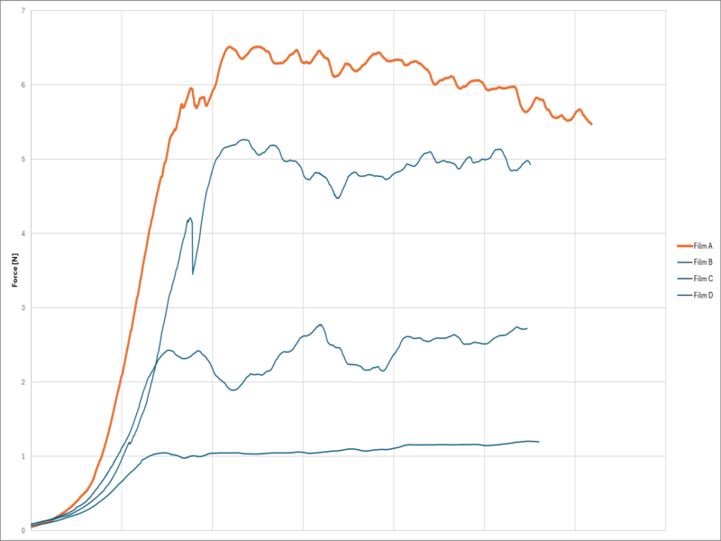
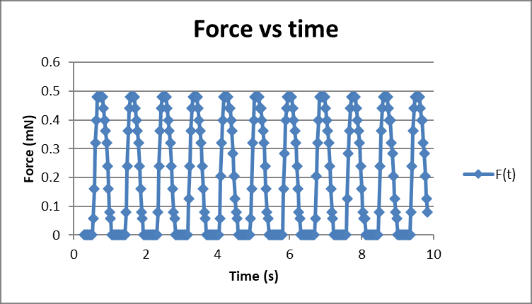
Each video is paired with a force–displacement plot that highlights mechanical response in detail. You can see not only the average peel strength, but also oscillations, plateaus, and sudden transitions in force—all linked to what’s happening at the interface.
This type of fine-scale signal would be drowned out on traditional machines. With FIBROPeel, you can correlate every curve fluctuation with the exact failure point in the video.
FIBROPeel allows you to test adhesives at the actual scale of use—not oversized or generalized approximations. By combining compact mechanics, sensitive force tracking, and visual correlation, it gives you better data, faster. Whether you're validating a surface treatment or comparing tape types, accurate testing at small scale leads to better design decisions.
FIBROPeel is built for precision adhesive testing—from concept to quality control.
Earlier this year, we reached an exciting milestone as a technology company: for the first time, we delivered one of our precision measurement systems to a client across the Atlantic. The customer – a global industry leader in advanced materials – became the first to receive this technology outside our home region.
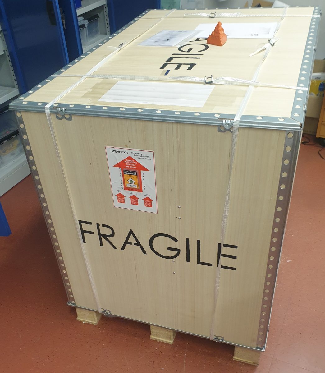
This wasn’t just a shipment; it was a landmark deployment that tested our planning, adaptability, and teamwork.
The client was looking for a solution that combined high-resolution measurement with flexible software integration – features not easily found in existing systems. After an extensive evaluation and multiple technical discussions, our technology was chosen.
For us, this validation highlighted the value of years spent developing, refining, and validating our devices with both academic and industrial partners.
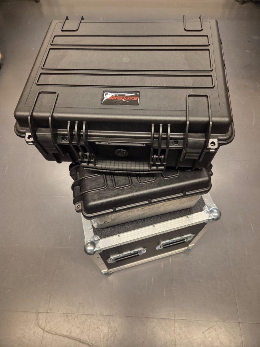
Getting the device ready for international shipment required careful coordination:
Once onsite, our engineers worked closely with the client’s team to commission the system, calibrate the setup, and train key users. It was rewarding to see our solution operate in a completely new environment, demonstrating both flexibility and robustness.
Of course, no first-time delivery comes without surprises. Despite extensive preparation, a few issues emerged during setup – including a minor software configuration mismatch and a mechanical detail that needed adjustment. Thankfully, these were resolved quickly on-site. These hiccups, while stressful in the moment, ultimately reinforced the importance of thorough simulation and checklists – lessons we’ve already applied to improve our internal processes for future deployments.

The delivery wasn’t just about technology – it was about trust. The client relied on us to provide a solution that worked from day one. While not every detail was perfect, our quick response and commitment ensured the system met expectations.
This reliability built confidence and laid the foundation for a strong long-term relationship.
Looking back, the project was a resounding success. We gained invaluable experience in:
As a team, we grew. As a company, we’re now better prepared for future international deployments – wherever they may be.
This first-of-its-kind delivery proved that progress comes with challenges, but also with opportunity. By solving problems and learning on the ground, we strengthened our technology and our capabilities as a company.
We look forward to the next chapter – delivering innovative solutions to clients worldwide.
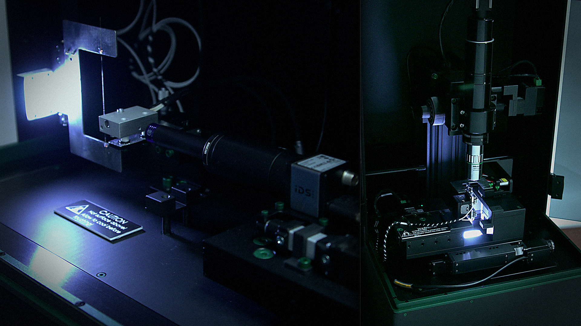
Let's say you have a small object and would like to know more about its shape than what a 2D image can tell you. Suitable methods for 3D imaging such samples are, e.g., microCT, nanoCT, laser profilometer, MRI, and OPT. Most of these techniques require expensive devices and might only be suitable for some sample sizes and types. Out of those mentioned above, Optical projection tomography(OPT) has been commonly used in biological and medical imaging fields. OPT is a method where the sample is rotated a full rotation between a light source and a camera, and multiple images are recorded during this rotation. A set of images is called a stack, and it is handled through various processes, and finally, an accurate 3D reconstruction is made out of the sample.
In micromechanical material characterization, it is crucial to know the accurate cross-sectional shape of the sample. In the case of synthetic fibres e.g. carbon, glass, or polymer fibres, cross-sections can be measured from a single projection. But in the case of natural fibres, single projection is not an accurate way to measure the cross-section of the sample. For example, flax fibres have constant variation in their cross-sections varying from elliptical, circular, or even almost square shapes. This variation is shown in Figure 1 with OPT reconstruction of a 10mm long section with a total of 830 million voxels. Another example is the twisting of a sample, which is typical for pulp fibres.

FIBROOpt is a device that combines conventional OPT with micro-robotics. This gives the possibility to image long samples with extreme resolutions. The device can calibrate itself up to the optical resolution of the used optics. The process is fully automated, and the user only has to choose which part of the sample is imaged. End result of the process is a voxel cloud that can be transformed into cross-sectional slices or a 3d model that can be imported into FEM software for accurate modeling of the behavior of the material.
So, why would you waste your time making microtomic slices to measure your samples locally and just save your energy and just use OPT? Hit us with a call, email, fill out the form or follow us @linkedin and we will guide you toward OPT measurements.
If you were interested in the shear properties of a composite structure, you would measure them conventionally on a laminate scale. Applicable tests would be e.g., short beam shear, v-notch shear or ±45° tension shear tests. Each of these tests requires a unique sample and usually additional sensors e.g., strain gauges or digital image correlation systems. When the setup is complex, it increases the amount of time needed for testing, material usage grows, and there are added sources of errors. And when researching natural fibres, surface treatments, or experimental materials, this scale might not be possible when materials are scarce. Then it might be wise to change to microscale measurements.
Micromechanical testing has been around for decades, and there are multiple methods to measure the interfacial shear strength (IFSS) of a fibre matrix interface. The most well-known methods are microbond, pull-out, and single fibre fragmentation tests. These methods have had problems, either in sample manufacturing or getting consistent results from the measurements. There is a rising interest at the moment in multiscale modeling, where microscale properties of the material are the starting point for understanding the laminate behavior of composite materials. Industries are also interested in new materials, e.g., natural fibres, lignin and/or cellulose-based carbon fibres, vitrimers, and thermoplastic composites. These have increased the need for rapid testing equipment, which does not require pilot-scale production of materials. The aforementioned drivers have been one of the key factors in the development of FIBRODrop and FIBROBond devices. They can create a large set of samples from a small amount of material and measure them in a hasty schedule.

FIBRODrop and FIBROBond devices together are an excellent choice for developing sizings, characterization of new materials, comparison of batches of products, or determining the material properties for models. For testing, you would only need ~30 cm of rowing or tow and 100g of thermoset resin (or a few granulates of thermoplastic polymer) to perform the microbond measurements.
So, why would you waste your time measuring on macroscale and just save your energy and start measuring in microscale today? Hit us with a call, email, fill out the form or follow us @linkedin and we will guide you toward microscale measurements.
Fibrobotics is honored to be one of the 6 companies that were admitted into the European Space Agency - ESA - Business Incubator program this summer. These startups will receive funding from ESA-BIC and Business Finland, and will receive support from ESA-BIC and Aalto Startup Center.
Read more and follow us in LinkedIn
Especially the applications of fibrous composites in miniature products, dental and other medical applications require accurate data of microscale mechanics. The characterization of adhesion between single filament and picoliter-scale polymer matrix usually relies on the experiments using so-called microbond (MB) testing. In this paper, a monolithic compliant based structure with an integrated Fiber Bragg Grating (FBG) sensor is developed and analysed. The developed strain-sensing CBPM-FBG holder shows excellent sensitivity during the MB tests for both synthetic and natural filaments, even at a low filament diameters as low as 7μm, making the monolithic compliant structure the first instrument capable of force-strain data output for bonded filament-droplet specimens.
"For the first time ever, force-filament strain data was systematically collected for droplet-filament specimens at a sampling rate of ≥50Hz when the integral FBG-CBPM specimen holder was operated in the Fibrobond MB tester; three different material systems were analyzed. FEA of the MB testing with glass filaments and epoxy droplets enabled fitting and exact interfacial CZM-based debond model and frictional sliding with a friction coefficient of 0.35." (Royson et al. 2021)